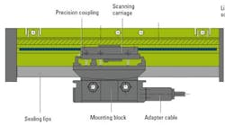
Linear encoders can position linear motors with repeatabilities ranging from several microns to a few nanometers. In addition to providing positioning data, most linear encoders also provide velocity data that the drive uses in commutating the motor. With the increasing use of linear motors, competition is heating up among the various encoder technologies. Over the next few years, engineers can expect to see many refinements to the repeatable accuracies of measuring linear motion.
The accuracy of linear encoders is a function of the scale graduation, the scanning method, the system mounting, and the signal processing electronics. At all mounted lengths, thermal factors affect the accuracy. In addition, deviations in the signal during a signal period also affect the position accuracy. Deviations in any of these areas ultimately affect the speed stability of the linear motor, even at low traversing speeds.
No vibrations, please
How and where an engineer mounts the encoder affects overall system accuracy. The flatness of the mounting surface, the accuracy of the machine guideways, and the encoder’s nearness to machine vibration all affect its ability to accurately scan the measuring scale. These factors affect sealed encoders less than exposed models.
With sealed encoders, the coupling is attached to the scanning carriage so that it is rigid in the measuring direction and flexible in the perpendicular direction. Otherwise, the scanned data for position and velocity would limit the bandwidth of the drive, limiting its command- signal response and ability to reject disturbances.
For exposed encoders, the scale or scale tape is rigidly fastened directly to the mounting surface to minimize hysteresis in the control loop. To reduce the affect of guideway errors on accuracy, engineers should mount the encoder as close to the machine guideway as possible.
The proper pitch
In addition to its affect on measurement accuracy, the fineness of the scale gradations also determines the degree of electronic enhancement (interpolation) needed to achieve the required resolution. Some encoders have a fine pitch scale, and are best suited for high resolution applications. Other encoder scales have a larger grating period (4 to 40 μm and above) and often rely on the interpolating electronics to provide the needed resolution.
Signaling for accuracy
The quality of the output signal, along with the signal period, also affect the amount of deviation. Exposed encoders typically have deviations of ±1% of the signal period over the measured length. Sealed encoders usually have deviations of ±2% of the signal period. Larger deviations not only reduce the repeatibility of the encoder, they can also cause speed variations and increase the power losses with the motor.
The transmission speed of the encoder output signal through the cabling to the drive may also affect the signal processing. The drive generally samples encoder data in intervals of less than 500 μsec. Feedback values for position and speed are usually available in less than 50 μsec. Serial transmission is inadequate for such demanding time requirements, so encoders use other output signals.
Sinusoidal output signals are best suited to applications with high traversing speeds and small measuring steps, such as those found in machining and positioning applications. They require digitizing circuitry to interpolate the signal to fit drive applications, but it depends on when the interpolation is done. Interpolating before the signals are sent to the electronics can result in high input frequencies that may limit the speed of the application.
TTL square-wave output signals include circuitry, often integrated in the mounting block, that digitizes sinusoidal scanning signals without interpolation. They provide two 90 degree electrical phase-shifted pulse trains and a reference pulse.
Some encoders transmit signals synchronized with a clock signal provided by the electronics. This makes it possible to transmit position values and parameters using only four signal lines.
Bending the light
Lastly, the effects of light diffraction affect position accuracy. If the grating periods are between 20 to 40 μm, the imaging method of photoelectric scanning is used. If the grating periods run between 8 to 4 μm, then the encoders use the interferential method. Both methods use a scanning reticle, a transparent phase grating that generates and superimposes the diffracted beam components. The light source is an LED with a condenser lens.
With the imaging method, the position deviation in one signal period is usually ±0.4 μm. With the interferential photoelectric scanning method, assuming proper mounting and high signal quality, the position deviation in a 2 μm signal period is ±0.02 μm.
The imaging method offers a choice of illumination configurations. The four-field scanning method transmits light through the scale to the photovoltaic cells. The scanning reticle contains four separate fields with line gratings, each offset by 1⁄4 of a grating period. Collimated light from an LED shines through the condenser lens and onto the scale. As the scanning unit moves, the line gratings of the scale and scanning reticle alternately align. Photovoltaic cells sense the resulting light-dark modulation and generate four sinusoidal current signals, phase-shifted to each other by 90 degrees electrical.
In the quasi-single field scanning method, the reflective steel scaletape has a grating period of 40 μm. The index grating consists of two interlaced phase gratings with differing diffraction characteristics. This scanning method is relatively insensitive to slight waviness of the scale tape. One scanning field generates all four scanning signals. Fluctuations in the light intensity have an equal effect on the four photocell signals. Thus, the sinusoidal output signals still have high quality, even in a slightly contaminated environment.
The interferential method of photoelectric scanning exploits light diffraction at the grating to produce the measured signal. When the scale moves, the light waves in the higher orders of diffraction undergo phase shifts that are proportional to the scale’s displacement. To evaluate these phase shifts, the different orders of diffraction are superimposed and brought into interference. The resulting light modulation lets the photovoltaic cells produce three 120-degree phase-shifted signals, which are converted to two 90-degree phase-shifted signals.
Dr. Hagl is department manager, Encoder Production, at Dr. JohannesHeidennhain, GmbH, Germany.


