True Cost of Ownership for Linear Position Sensors, Part 2
To help you evaluate the True Cost of Ownership (TCO) of commonly used industrial linear position sensors, our first article identified the four most commonly utilized industrial position-sensing technologies. It also posed questions to ask yourself about various position-sensor application issues to assist you in making an optimum choice of sensor from a technical and an economic perspective.
Our second article examines the strengths and weaknesses of these technologies, presents a comparison chart of their specification parameters together with a brief explanation of what those specifications mean, and helps you to focus on the technical aspects of a TCO evaluation.
The most commonly utilized industrial position sensing technologies are linear variable differential transformers (LVDTs), linear variable inductance transducers (LVITs), magnetostrictive linear displacement transducers (MLDTs, also known as LDTs), and linear resistance potentiometers (POTS).
Linear Resistance Potentiometers (POTS)
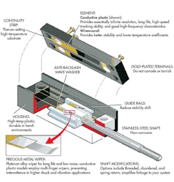
POTS are simple position sensors that move a sliding contact along a fixed linear-resistance element inside an enclosure. The object whose position is going to be measured is coupled to a shaft attached to the slider. The ends of the resistance element are connected to low-voltage dc and the pot acts as a voltage divider. An output voltage proportional to the slider position is developed between the slider connection and one end.
The attractions of POTS are their ease of hook up and relatively low cost. POTS with polymer resistance elements generally offer good linearity, resolution, and repeatability to begin with, but their repeatability typically suffers degradation with increasing numbers of cycles of operation. POTS also have excellent stroke-to-length ratios, but they can be easily broken or severely damaged in the event of a mechanical overload. POTS usually are limited in their analog output to a dc voltage equal to or less than their input voltage. The chart in this article compares potentiometers with other position-sensing technologies.
Linear Variable Differential Transformers (LVDTs)
An LVDT is a primary helically wound transformer with a primary and two identical secondary transformers. As an electrical transformer, it operates from low-voltage ac at an audio frequency. A cylindrical movable “core” of high-permeability magnetic material couples the primary voltage to the secondaries, which are connected as series opposing. Over a specific range of core motion, the output voltage of the differentially connected secondaries varies linearly with movement of the core.
In operation, the workpiece, whose position is being measured, attaches to the core. The core does not need any mechanical contact with the LVDT coils. This contactless operation means that an LVDT position sensor doesn’t wear out and is impervious to mechanical overload. LVDTs are characterized by excellent repeatability and resolution, as well as long life and high reliability.
LVDTs come in two forms. The first is an AC-LVDT, which is most often used in hostile environments that involve extreme temperatures of 175°C to values higher than 200°C, and high vibration and shock. An example of the latter may be down hole in drilling oil wells, which utilizes separate remote support electronics located in a more benign environment than the LVDT itself.
The second type of LVDT is called a DC-LVDT, which has built-in electronics that accepts dc power input and produces an analog dc output. A DC-LVDT may be more convenient to use in a lot of applications, but the integral electronics also limits the environments—especially ambient temperature—in which it can operate.
One of their drawbacks is their comparatively poor stroke-to-length ratio, which makes the sensor quite long when measuring position changes over a few inches. AC-LVDTs also have a high installed cost because of the need for a separate signal-conditioning module. However, DC-LVDTs are broadly used in all manner of industrial automation and assembly machinery. Their installed cost is moderate, but depends greatly on range.
Both types of LVDTs typically have a hollow tube form factor with a free or captive core, but spring loaded units are offered in short ranges. The table below shows a more complete comparison of both types of LVDTs with the other common industrial position-sensor technologies.
Magnetostrictive Linear Displacement Transducers (MLDTs)
Magnetostrictive linear displacement transducers operate by measuring the time it takes a mechanical torsion pulse wave to travel along a waveguide made of a magnetostrictive metal. Thus, an MLDT is a time-of-flight (TOF) sensor system like radar or sonar. Torsion pulse can be generated or detected in several ways, all of which rely on the interaction of the field of a permanent magnet mounted on the moving object with the magnetostrictive waveguide.
In operation, measuring the time interval from when the pulse was launched until it’s reflected back can be accomplished with high accuracy. Thus, an MLDT can offer a relatively high precision position measurement. Although they display excellent resolution, repeatability, and linearity, MLDTs typically have a dead zone at either end of their range, which results in reduced stroke-to-length ratio.

MLDTs are much more costly than other industrial position-sensor technologies for a similar range. Consequently, applications use them where measurement precision is an overarching requirement. Their most common form factor is a small-diameter, sealed, stainless-steel tube, typically 10 mm, welded to a larger metal enclosure that contains the electronics needed to operate the sensors, with a ring magnet assembly over the tube as the moving element. The sealed enclosures’ male O-ring port thread permits their usage in a hydraulic cylinder with a suitable O-ring boss at one end (embeddable versions are available, too).
Like the previously discussed position sensors, MLDTs are contactless, so they do not wear out. However, their internal waveguide is suspended within their tubular probe and is susceptible to effects from shock and vibration, which can impact their reliability and service life. They also have a limited update-rate capability, because the TOF measurement must allow enough time for the pulse to travel to, and be detected at, the maximum range. The chart shows the comparative strengths and weaknesses of MLDTs.
Linear Variable Inductance Transducers (LVITs)
LVITs are similar to DC-LVDTs in that they operate without contact between their inductive probe and their moving element, and they use built-in electronics. But they offer a favorable stroke-to-body length ratio at a significantly lower initial cost than a DC- LVDT.
They operate via changes in the inductance of their probe coil caused by eddy currents in the surface of a conductive moving element called a spoiler, which moves within the inductor’s magnetic field. The integral smart electronics converts the inductance change into an analog dc output.
LVITs offer excellent repeatability along with good resolution and linearity. Their construction and contactless operation enables them to withstand substantial shock and vibration environments, and the internal electronics includes ambient temperature compensation. Because it’s contactless, an LVIT position sensor doesn’t wear out and is resistant to mechanical overload.
LVITs come in a variety of configurations for standalone position sensing, or with a pressure-sealed probe to operate inside a hydraulic cylinder that has a gun-drilled blind hole in its ram. The pressure-sealed LVITs have a male O-ring port thread that permits their use in a hydraulic cylinder with a female O-ring boss on one end, or they can be completely embedded inside a cylinder.
The installed cost of an LVIT is low compared to other technologies. Thus, as standalone position sensors, they compete with DC-LVDTs, offering most of the same benefits at much less cost, along with a much better stroke-to-length ratio. They, too, are available in spring-loaded versions for shorter ranges. LVITs also compete strongly against POTS because they offer contactless operation and equivalent stroke-to-length ratios at comparable cost.
Pressure-sealed- probe LVITs compete with MLDTs for use inside of hydraulic cylinders, at lower initial cost and without requiring that the cylinder piston be machined to accept a ring magnet. These specific features lower their installed cost in cylinders for mobile equipment and industrial fluid-power applications. LVITs are compared to the other common industrial position sensors in the table below.
Sensor Inputs and Outputs
One of the often overlooked considerations in selecting an industrial position sensor is the choice of input and output (I/O). Typical sensor inputs are: +24 V dc for devices with integral electronics (DC-LVDTs, LVITs, MLDTs), particularly for automation systems, +10 V dc for POTS, and +5 V dc for many sensors used with embedded microcontrollers.
All of the sensors reviewed offer one or more analog outputs, and a few offer some kind of digital output as well. Utilizing digital outputs usually requires some understanding of network protocols and related issues and the use of specific cabling, which often leads to higher installation costs. Thus, most industrial applications tend to utilize analog outputs.
When the output of the sensor is being input to a PLC or data-acquisition system, dc voltage is the preferred sensor output, especially when the system is located close to the sensor. If the sensor is located some distance from the rest of the system, a 4- to 20-mA current-loop output is often more useful and desirable, but typically requires a 24-V dc power input.
Understanding the Linear Position Sensor Chart
The comparison chart evaluates the important specifications and parameters of the four analog-output position-sensor technologies commonly used in industrial position-measurement applications. The ratings are based on an aggregate assessment of sensors using these technologies, but recognize that specific sensors may differ in some respects.
Range: Many industrial position sensors are offered in full ranges, from fractions of an inch to 20 inches. However, both LVITs and MLDTs are available in longer ranges at modest incremental cost.
Resolution: This is a key parameter in modern measuring systems to indicate the smallest change in a sensor’s input that results in an output change. Although sometimes specified as bits (10-bit resolution equals 1 part in 1024, or 0.1%; 12 bits equals 1 part in 4096, or 0.025%), in analog sensors it’s more often specified as a percentage of full span output (%FSO). Many analog sensors offer infinite resolution, but when used with digital electronics, resolution is limited by the number of bits in the analog-to-digital conversion process. Resolution is one of the two fundamental limiting factors in the application of a sensor, the other limiter being repeatability. Essentially, no sensor can give better performance than its resolution and repeatability permit.
Repeatability/Hysteresis: Repeatability is the single-most important specification parameter for a sensor. Repeatability is a measure of the variation in output for repeated trials of exactly the same sensor input applied from the same direction. Its magnitude is determined statistically and usually expressed as a percentage of full range. Hysteresis is a measure of the variation in output at a particular position depending on the direction of motion to that position. Some sensors may have sources of friction, etc. which can introduce hysteresis in its output.
Nonlinearity: Nonlinearity (a.k.a. linearity error) is a measure of the maximum deviation of a sensor’s output from a prescribed straight line, most often a best-fit line. Typically, the reference line is developed by a statistical process (least squares) or drawn between the end points of the output. Smaller linearity error makes it easier to interpret measurements using a sensor calibrated with a limited number of data points, or calibrated only at the end points. With a highly repeatable sensor, digital electronics can be used to linearize a position-measuring system’s output to any desired level within the limit of resolution.
Temperature characteristics: Temperature coefficients (tempcos) quantify the deviation of a sensor’s output due to changes in its thermal environment, both hotter and colder. There’s often a tempco for offset, which shifts the sensor is zero point, and another tempco for scale factor, which affects the sensor’s calibration. As noted with nonlinearity, digital electronics can be used with a highly repeatable sensor along with a temperature probe to compensate a measuring system’s output over any reasonable temperature range.
Dynamic response: In a sensor, this may be limited by elements of its mechanical construction, such as inertial mass and friction, or by electronic factors like operating or filter frequency, or by update rate.
Vibration and shock sensitivity: This is determined by a sensor’s mechanical construction, including internal masses. For MLDTs, the waveguide support structure is potentially susceptible to these factors. POTS have potential for wear out from vibration if the slider isn’t being moved by the workpiece. LVITs and DC-LVDTs both have built-in electronics that are usually fully potted to enhance their mechanical robustness. AC-LVDTs are regarded as the optimum sensor to withstand the harshest environments.
Life and reliability: Potentiometers develop wearout at the sliding contact, especially with any dither. Magnetostrictive sensors will fail if there’s failure with the waveguide support structure. However, in general, electronics built into sensors tend to become the most likely contributors to reliability issues, based on the mean time between failure (MTBF) of their many components.
Stroke-to-length ratio: This factor, which compares the measuring range of a sensor to its overall length, is often a consideration in OEM position-sensor applications that have limited space for the sensor. It can also be important in sensor installations on assembly machines and factory automation equipment.
Initial cost: Potentiometers often have the lowest initial cost because they require no electronics. All other sensors in the table require some built-in electronics. LVITs also have low initial cost, even with integral electronics. AC-LVDTs have high initial cost— in addition to the base sensor cost, they need an external signal conditioner to operate.
Installed cost: This is a combination of purchase price, cost of installation hardware and software, labor to mount/install the sensor, and the cost of hooking the sensor up to the rest of the measuring system.
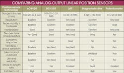
When evaluating the various parameters listed in this comparison chart, it’s best to identify the three or four specifications most critical to your application. These specifications should rank high on your priority list. For example, if you require fast action in your process system, then dynamic response is important. If you have only a limited space, then stroke-to-length ratio is a key point. If there’s some danger of mechanical overload, then that becomes a major consideration. If you have a reliability or service life issue, that points you toward certain technologies.
Be prepared for some potential tradeoffs, because some features may cost more or preclude other desirable features. But if you can prioritize the critical parameters or features, the process will sharpen your focus and the remaining issues usually become less of a problem.
Using your specification priority list to help you choose the appropriate sensing technology, and looking at your answers to the queries from the previous article, you should now have enough information to be able to apply various costs to your sensor system, which will be described in the third article in this series.
Harold G. Schaevitz is CEO and president of Alliance Sensors Group, a division of H.G. Schaevitz, LLC.
About the Author
Voice Your Opinion!
To join the conversation, and become an exclusive member of Machine Design, create an account today!

Leaders relevant to this article: