What's the Difference Between AC Induction, Permanent Magnet, and Servomotor Technologies?
This file type includes high resolution graphics and schematics when applicable.
Engineers today are tasked with applying myriad motor technologies because most rotary motion is ultimately powered by electric motors. here we outline the capabilities of driven AC induction motors, permanent-magnet motors, and servomotors — the three major technologies with partially overlapping functionalities for larger, higher-end applications requiring precisely metered torque, speed, or positioning.
1st of 3 technologies: AC induction motors
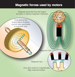
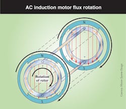
In all its iterations, the induction motor induces magnetism that is leveraged to output rotary motion. The stationary outer stator is connected to an external electrical power source; this is fed to the rotor’s poles in a rotating progression that causes revolutions of the magnetic field within the motor. Conducting bars in the rotor interact with the stator’s magnetic fields; current is induced in those bars, which in turn generate magnetic fields that are attracted to those of the stator.

As the rotor’s induced current and magnetism cause it to follow the field generated by the stator, rotary motion is output.
Because an AC induction motor increases the flux enclosed by its stationary coils, it is a transformer with a rotating secondary (rotor). The rotor current’s effect on the air gap flux causes torque.
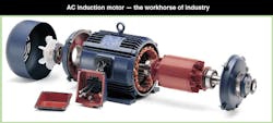
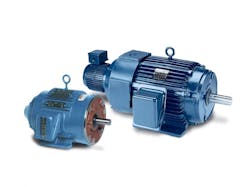
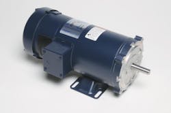
AC induction motors are built by manufacturers according to established National Electrical Manufacturers Association (NEMA) standards in myriad fractional and integral horsepower ratings and associated frame sizes. These AC induction motors are quite common — the workhorse of industry.
AC induction motor technology overview
An induction motor’s stator consists of a stack of thin, highly permeable steel laminations with slots; the laminations are either secured in a steel or cast-iron frame that provides a mechanical support. The windings that accept the external power supply are run through the slots.
The AC inductor rotor assembly resembles a cage consisting of aluminum or copper conducting bars connected by short-circuiting end rings — hence the nickname squirrel cage for induction motors.
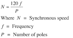
The rotor also has laminations; radial slots around the laminations contain the bars. As mentioned, the rotor turns when the moving magnetic field induces current in the shorted conductors, and the rate at which it rotates is the motor’s synchronous speed — determined by power-supply frequency and the number of stator poles.
Synchronous speed is the fastest theoretical speed a motor can possibly spin — when the rotor spins at the same speed as the motor’s internal rotating magnetic field. In practice, an AC induction motor is an asynchronous motor (in which the rotor lags field speed) so its rotor must spin more slowly than the field, or slip. This allows the induction of rotor current to flow, and production of torque to drive attached load while overcoming internal losses.
AC induction motor capabilities for force, torque, and speed: AC induction motors are either single-phase or poly-phase. Single-phase AC motors power myriad low-horsepower commercial and industrial applications where three-phase power is impractical; they’re not efficient, but can last a lifetime.
They’re also classified by how they are started, as these motors alone develop no starting torque, but require external means for initial actuation.
The simple split-phase (induction-start-induction-run) motor has a small-gage start winding with fewer turns than the main winding to create more resistance and put the start winding’s field at a different electrical angle than that of the main — causing the motor to rotate until it reaches 75% of rated speed. Then the main winding of heavier wire keeps the motor running. This inexpensive design develops high starting current (700 to 1,000% of rated) so prolonged starts cause overheating. Suitable applications include small grinders, blowers, and low-starting-torque applications requiring up to 1/3 hp.
Split-capacitor motors are common but slowly being replaced with more efficient motors and variable-frequency drives (VFDs), which we’ll explore later. Split-capacitor motors have a run-type capacitor permanently connected in series with the start winding, making the latter an auxiliary winding once the motor reaches running speed. Starting torques are 30 to 150% of rated load, unsuitable for hard-to-start applications. However, starting current is less than 200% of rated load current, making them suitable for cycling or frequent reversals — in fans, blowers, intermittent adjusting mechanisms, and quick-reversing garage door openers.
Most powerful of all single-phase types, capacitor-start-capacitor-run motors have a start capacitor in series with auxiliary winding, plus a run-type capacitor in series with the auxiliary winding for high overload torque. Some have lower full-load current and higher efficiency — so operate more coolly than other single-phase motors of comparable horsepower. Cost is higher, but these motors are indispensible in woodworking machinery, air compressors, vacuum pumps, and other 1 to 10-hp high-torque applications.
Lastly, inexpensive shaded-pole single-phase motors have only one main winding. Starting is through a copper loop partially covering a portion of each motor pole — causing the magnetic field in the ringed area to lag that in the unringed portion. The reaction of the two fields causes shaft rotation; varying voltage controls speed. These are disposable motors, and common in household fans; efficiency is 20% or lower.
Three-phase asynchronous motors
Far and away the most common industrial motor is the three-phase AC induction motor. Single-phase motors are versatile, but three-phase (and other poly-phase) motors offer higher power and efficiency, and require no switch, capacitor, or relays. More specifically, three-phase induction motors have high starting torque, because six poles (only 60° apart) work in pairs to boost the power factor — also useful in large industrial applications.
Oversizing and undersizing
Carefully define application requirements before choosing a replacement motor, or one for a new design: An undersized motor exhibits electrical stresses and premature failure. An overly powerful motor (with high locked-rotor and breakdown torques, for example) can damage the equipment it drives, and runs at less than full rated load, which is inefficient.
NEMA classifies general-purpose three-phase motors as A, B, C, or D according to their electrical design. For example, NEMA Design C motors have higher starting torque with normal start current and less than 5% slip.
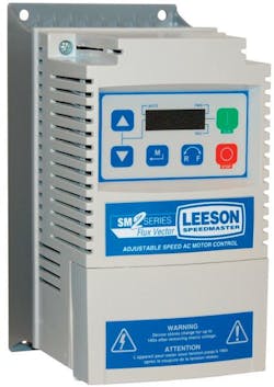
Some of these motors are connected directly to line power with a basic switch; others are fitted with wye-delta windings or soft starters. However, roughly one-third of all industrial designs are variable-load applications, and in these designs, motors are increasingly being driven by VFDs — which have (thanks to increasingly sophisticated yet affordable semiconductors and circuitry) proliferated over the last two decades.
In these devices, pulse-width modulation (PWM) is used to vary motor voltage. In turn, solid-state switches such as insulated gate bipolar transistors (IGBTs) or gate turn off SCRs (GTOs) execute PWM. Here, AC line voltage is converted to DC and then reshaped so that motor speed varies with the frequency of the pulses in the output voltage. PWM AC drives allow wide speed ranges, programmable acceleration and deceleration ramps, and good energy efficiency; speed and torque precision can in some cases match that of DC systems.
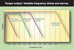
• In its simplest iteration, Volts-per-Hertz VFD operation holds the ratio of voltage and frequency constant, by tracking voltage magnitude. This prevents magnetic saturation (at which a motor’s rotor cannot be magnetized further, causing high currents); voltage to be applied is calculated from the applied frequency required to maintain air-gap flux — a method that provides passable speed control, though no direct control of motor torque.
• Sensorless vector control also modulates frequency but measures (and compensates for) slip by determining the amount of current in phase with the voltage for approximated torque current — for both magnitude and angle between current and voltage. This helps to keep the motor running at target speed even under varied load.
• Slightly more sophisticated, flux vector drives leverage the fact that in induction motors, some current magnetizes or fluxes the rotor to magnetically couple it to the stator.
Flux vector drives hold this flux current at the minimum required to induce a magnetic field, while independently modulating torque-producing current pulsing through the stator.
Finally, the VFD iteration called field-oriented control pairs a drive’s current regulators with an adaptive controller to independently meter and control motor torque and motor flux. This kind of drive can be paired with an encoder for closed-loop servocontrol, but its consistent performance doesn’t typically require feedback. Torque output is consistent from zero to full load over myriad speeds.
AC induction motor limitations
Even under sophisticated VFD control, AC induction motors exhibit inherent efficiency limitations and can require an encoder for feedback if low-speed accuracy is required. In addition, retrofitting an existing design with a new VFD can be troublesome, particularly when equipped with older motors.
Why? Its inverter’s synthesized AC waveform accelerates heating (though advances continue to improve the waveform to more closely approximate an AC sine wave.) Extended operation of a VFD-powered motor at less than 50% of base speed is also unacceptable; modern inverter-duty motors have higher insulation ratings, but extreme cases require a separately powered cooling fan.
In fact, the waste heat generated by any AC motor is capable of degrading the insulation so essential to motor operation. Stator insulation prevents short circuits, winding burnout, and failure: Magnet wire coating insulates wires within a coil from each other; slot cell and phase insulation (composite sheets installed in stator slots) shield phase-to-ground; stator varnish dip boosts moisture resistance and overall insulation.
NEMA sets specific temperature standards for motors of various enclosures and service factors (of 1.5 or more in most cases.) These standards are based on thermal insulation classes — often B, F, and H. Maximum winding temperature ratings are total temperatures, based on 104° F maximum ambient plus the temperature rise generated by motor operation. 5 hp and greater, premium efficiency, and inverter-duty motors typically have Class F insulation. Beyond that, many manufacturers design their motors to operate more coolly than their thermal class definitions. Class H insulation is rarer, reserved for heavy-duty, hot, or high-altitude conditions.
Another consideration is cycling: Motors built for frequent reversals can withstand it, but start-stop cycles in others can cause overheating, because a typical motor under these conditions draws five to six times the rated running current, which accelerates heating. NEMA limits three-phase continuous-duty induction motors to two starts in succession before allowing the motor to stabilize to its maximum continuous operating temperature.
Finally, the VFDs commonly used to drive three-phase AC induction motors are sensitive to inertia, horsepower, motor lead length, and power quality, so must be programmed with full-load and no-load amps, base speed and frequency, and motor voltage when initially connected to a new motor. Typically VFDs also require tuning, during which motor response and electrical characteristics are logged.
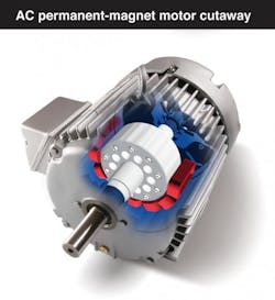
2nd of 3 technologies: Permanent-magnet AC motors
One proliferating option, permanent magnet ac (PMAC) motors, has functionalities that partially overlap with those of both ac induction and servomotors for larger, higher-end applications requiring precisely metered torque, speed, or positioning.
In PMACs, magnets mounted on or embedded in the rotor couple with the motor's current-induced, internal magnetic fields generated by electrical input to the stator. More specifically, the rotor itself contains permanent magnets, which are either surface-mounted to the rotor lamination stack or embedded within the rotor laminations. As in common ac induction motors, electrical power is supplied through the stator windings.
Permanent-magnet fields are, by definition, constant and not subject to failure, except in extreme cases of magnet abuse and demagnetization by overheating. PMAC, PM synchronous, and brushless ac are synonymous terms.
The magnets in permanent-magnet motors
- Rare-earth elements are those 30 metals found in the periodic table’s oft-omitted long center two rows; they’re used in many modern applications. Magnets made of rare-earth metals are particularly powerful alloys with crystalline structures that have high magnetic anistropy — which means that they readily align in one direction, and resist it in others.
- Discovered in the 1940s and identified in 1966, rare-earth magnets are one-third to two times more powerful than traditional ferrite magnets — generating fields up to 1.4 Teslas in some cases.
- Permanent magnets are used in MRI machines, portable electronic devices, hysteresis clutches, accelerometers, and — last but not least —permanent-magnet rotary and linear motors.
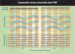
Back-electromotive force (EMF) is voltage that opposes the current that causes it. In fact, back EMF arises in any electric motor when there is relative motion between the current-carrying armature (whether rotor or stator) and the external magnetic field. As the rotor spins (with or without power applied to the windings) the mechanical rotation generates a voltage — so, in effect, becomes a generator. Typical units are (V/krpm) — volts/(1,000 rpm).
A PMAC motor has a sinusoidally distributed stator winding to produce sinusoidal back EMF waveforms.
All PMAC motors require a matched PM drive for operation; they are not designed for across-the-line starting.
PMAC-compatible drives (known as PM drives) substitute the more traditional trapezoidal waveform's flat tops with a sinusoidal waveform that matches PMAC back EMF more closely, so torque output is smoother. Each commutation of phases must overlap, selectively firing more than one pair of power-switching devices at a time. These motor-drive setups can be operated as open-loop systems in midrange performance applications requiring speed and torque control. Here, PMAC motors are placed under vector-type control.
In fact, though PMACs require a drive specifically designed for PM motors, the PM drive setup is most similar to flux vector drives for ac induction motors, in that the drive uses current-switching techniques to control motor torque — and simultaneously controls both torque and flux current via mathematically intensive transformations between one coordinate system and another.
These PM drives use motor data and current measurements to calculate rotor position; the digital signal processor (DSP) calculations are quite accurate. During every sampling interval, the three-phase ac system — dependent on time and speed — is transformed into a rotating two-coordinate system in which every current is expressed and controlled as the sum of two vectors.
In PMAC motors, speed is a function of frequency — the same as it is with induction motors. However, PMAC motors rotate at the same speed as the magnetic field produced by the stator windings; it is a synchronous machine. Therefore, if the field is rotating at 1,800 rpm, the rotor also turns at 1,800 rpm — and the higher the input frequency from the drive, the faster the motor rotates.
Most manufacturers of synchronous motors hold pole count constant so input frequency dictates the motor's speed. For example, for a 48-frame motor with six poles, the motor's input frequency from the drive must be 90 Hz to obtain 1,800 rpm. To extract the same speed from a 10-pole 180-frame motor, input frequency must be 150 Hz. To calculate required input frequency (Hz) when the number of poles and speed are known:
PMAC motors are suitable for variable or constant-torque applications, where the drive and application parameters dictate to the motor how much torque to produce at any given speed. This flexibility also makes PMACs suitable for variable-speed operation requiring ultra-high motor efficiency.
Synchronous motors, and switched reluctance operation
- A permanent magnet AC (PMAC) motor is a synchronous motor, meaning that its rotor spins at the same speed as the motor’s internal rotating magnetic field. Other AC synchronous technologies include hysteresis motors, larger DC-excited motors, and common reluctance motors. The latter includes both a stator and rotor with multiple projections; the stator’s poles are wrapped with windings that are energized, while the rotor’s magnetically permeable steel projections act as salient poles that store magnetic energy by reluctance — leveraging the tendency of magnetic flux to follow the path of least magnetic reluctance in order to repeatedly align the rotor and stator poles.
- Note that this switched-reluctance motor iteration can be built to deliver up to 200 hp, overlapping with induction and PMAC motor capabilities. In switched-reluctance motors, the stator coils are synchronously energized with rotor rotation, with overlapping phases. While reluctance motors are typically used as open-loop steppers, their switched-reluctance derivative (also sometimes called variable reluctance) is typically operated under closed-loop control. In fact, stepmotors are somewhat similar to switched reluctance, and step to each defined rotor position, resulting in high repeatability and accuracy.
- Switched-reluctance motors produce high efficiency and control, and produce 100% torque at stall indefinitely — useful for applications requiring holding. Finally, though torque ripple must be overcome, switched-reluctance motors can be operated at higher speeds than PMACs, as they lack back-EMF constraints.
Cogging — the unwanted jerking during motor spinning from repeatedly overcoming the attraction of permanent magnets and the stator's steel structure — is often associated with PM motors. Particularly at startup, cogging arises from the interaction of the rotor magnets and stator winding when it is energized, due to harmonics. Cogging in turn causes noise, vibration, and non-uniform rotation. Many methods for reducing cogging can be leveraged to eliminate torque and speed ripple. Some PMAC motors are designed with more rotor poles than equivalent ac induction motors, which helps reduce these issues.
Closed-loop functionality
In specialty cases, PMAC motors are employed in closed-loop configurations using speed feedback. Feedback allows the drive to track the exact rotor position — to provide true infinite speed range, including full torque at zero speed. The speed reference required from an external source can be an analog or encoder signal, or a serial command from a feedback device on an axis one wishes to follow. This is normally a velocity signal, sometimes further processed in the drive before it is used as a command.
Limitations and challenges
PMAC speed is limited by back EMF because the latter increases directly with motor speed. The motor is connected to the electronic drive and its electronic components are designed for a maximum voltage above rated drive voltage. Normally, the motor and controls are designed to operate well below the maximum voltage of the components. However, if motor speed exceeds the design speed range (either powered from the control or being driven by the load) it is possible to exceed the maximum voltage of the drive components — and cause failures. Note that drives are capable of limiting motor back EMF when operating properly. However, if the drive faults and loses control during overspeed, it cannot protect itself.
In addition, PMAC motor control requires some technical knowledge for implementation: All commercially available PMAC motors require a PM-compatible drive to operate, although there is ongoing research in the development of a line-start PMAC motor.
Saliency
- In reference to PMAC motors, saliency refers to the difference in motor inductance at the motor terminals as the motor rotor is rotated. This difference corresponds to alignment and misalignment of the stator’s rotor — a characteristic that a motor’s drive tracks to monitor rotor position during operation.
Not all ac drives are suitable for operation of PMAC motors; only drives specifically designed for permanent magnet motor compatibility are suitable. Here, a parameter in the drive programming often allows an operator to set the drive for a PM motor. Some drives not specifically designed for this use can run and control PM motors, though performance is degraded — and one can damage the motor or drive if they are mismatched.
Axial and radial flux motors
- As with other motor designs that include permanent magnets, PMAC axial flux motors exist. In these motors, magnetic force (through the air gap) is along the same plane as the motor shaft — along the motor length. Axial flux can be thought as having the same orientation as disc brakes on a regular vehicle, as the disc rotates like the rotor in an axial flux design. Radial flux motors are the more traditional design, in which the magnetic force is perpendicular to the length of the motor shaft.
- A design’s form factor determines which orientation is most suitable: Does the machinery require a longer, skinnier radial motor or is a “pancake” axial design more appropriate? The final determining factor may be cost as the axial design, once tooled for production, provides equivalent torque but uses less active material for better power density. Though not yet suitable for elevator applications, engineers are developing PMAC radial motors to incorporate axial air-gap PMAC designs into elevators sans machine rooms.
Finally, high current or operating temperatures can cause the magnets in PMAC motors to lose their magnetic properties. Permanent magnets, once demagnetized, cannot recover, even if current or temperature returns to normal levels. PM drives reduce the risk of high-current demagnetization with over-current protection. Some motor designs further minimize the possibility of demagnetization with high-temperature magnets, integrated thermostats, and restricted motor operating temperature.
3rd of 3 technologies: Servomotors
Servomotors are motors that use feedback for closed-loop control of systems in which work is the variable. AC induction motors designed for servo operation are wound with two phases at right angles. A fixed reference winding is excited by a fixed voltage source, while the control a variable control voltage from a servo-amplifier excites the winding. The windings are often designed with the same voltage-to-turns ratio, so that power inputs at maximum fixed phase excitation, and at maximum control phase signal, are in balance. Any motor designed for servo use is typically 25 to 50% smaller than other motors with similar output, and the reduced rotor inertia makes for quicker response. For example, AC servomotors are used in applications requiring rapid and accurate response characteristics — so these induction motors have a small diameter for low inertia and fast starts, stops, and reversals. High resistance provides nearly linear speed-torque characteristics for accurate control.
Commutation basics
- Commutation refers to how current is precisely routed to a brushed DC rotor’s array of coils, to generate the torque needed via brushes and a commutator. A commutator is mounted on the rotor shaft and includes pads, on which the brushes rest.
- Current is conducted from the brushes to the commutator and then to the connected coils as the rotor spins. Sometimes the term commutation is used to refer to brushless DC motor operation, even though electronics and a sensor on the rotor shaft replace any brushes or commutator. In this case current is still switched but by electronics.
- The term loses meaning in the world of AC motors, though sometimes refers incorrectly to how AC voltage is generated in the drive.
Wound-field DC motors (with copper segments in the rotor connected by magnetic-wire windings, and stator windings) are another option. More often, however, compact brush DC motors (which employ permanent magnets affixed to the inside of the motor frame, plus a rotating wound armature and commutating brushes) are used as servomotors, because speed control is easy: The only variable is voltage applied to the rotating armature. There are no field windings to excite, so these motors use less energy than wound DC designs, and have better power density than wound-field motors. Servo-built brushed DC motors also include more wire wound onto the laminations, to boost torque.
DC servocontrol: Sophisticated
Three-phase PMDC motors (brushless motors) are also commonly used for servo applications. Most brushless DC windings are interconnected in an array, and most units are fitted with a trio of Hall sensors at one stator end. These Hall sensors output low and high signals when the rotor’s south and north magnet poles pass — to allow the following of energizing sequence and rotor position.
Permanent-magnet DC motors in servo applications
- Today, many PM motors are DC and used in servo applications requiring adjustable speed. For quick stops, these can minimize mechanical brake size (or eliminate the brake) by leveraging dynamic braking (motor-generated energy fed to a resistor grid) or regenerative braking (motor-generated energy returned to the ac supply). In addition, PMDC motor speed can be controlled smoothly down to zero, followed immediately by acceleration in the opposite direction without power circuit switching. In typical three-phase brushless DC motors, energization is controlled electronically. In some designs, permanent magnets are installed on the stator. More common designs include stators with stacked steel laminations and windings through axial slots; permanent magnets are installed on the rotor. Here, the stator winding is trapezoidally wound to generate a trapezoidal back EMF waveform with six-step commutation. Brushless DC switches energize changing pairs of motor phases in a predefined commutation sequence. Most units are fitted with a trio of Hall sensors at one stator end, to allow the following of energizing sequence and rotor position. Output torque has considerable torque ripple, which occurs at each step of the trapezoidal commutation. However, due to a high torque-to-inertia ratio, brushless DC motors respond quickly to control-signal changes — making them useful in servo applications.
In their most basic form, the drive for a servomotor receives a voltage command that represents a desired motor current. The servomotor is modeled in terms of inertia (including servomotor and load inertia) damping, and a torque constant. The load is considered rigidly coupled so that the natural mechanical resonance is safely beyond the servocontroller’s bandwidth. Motor position is usually measured by an encoder or resolver coupled to the motor shaft.
A basic servocontrol generally contains both a trajectory generator and a PID controller: The former provides position setpoint commands; the latter uses position error to output a corrective torque command that is sometimes scaled to the motor’s torque generation for a specific current (torque constant.)
Servomotor capabilities for force, torque, speed, and other factors: Servocontrol exhibits less steady state error, transient responses, and sensitivity to load parameters than open-loop systems. Improving transient response increases system bandwidth, for shorter settling times and higher throughput. Minimizing steady-state errors boosts accuracy. Finally, reducing load sensitivity allows a motion system to tolerate fluctuations in voltage, torque, and load inertia.
Typically, a profile is programmed for instructions defining the operation in terms of time, position, and velocity: A digital servocontroller sends velocity command signals to an amplifier, which drives the servomotor. With the help of resolvers, encoders, or tachometers for feedback (mounted in the motor or on the load) the controller then compares actual position and speed to the target motion profile, and differences are corrected.
Servomotor limitations
Most importantly, the increased performance of servomotor designs comes at dramatically increased cost.
In addition, there are two situations in which servomotor efficiency declines — low voltage and high torque. In short, servomotors are most often employed because of their ability to produce high peak torque, thus providing rapid acceleration — but high torque often requires that servomotors run two to three times their normal torque range, which degrades efficiency.
Finally, servos are designed to operate over a wide range of voltages (as this is how their speed is varied) but efficiency drops with voltage.Comparing induction motors, AC permanent-magnet motors, and servomotors
Designers and motor personnel benefit from finding a supplier that’s an experienced resource of information to help in pragmatic motor selection. Involve application specialists as early as possible, as they can help develop prototypes, custom electrical and mechanical designs, mountings, and gearboxes. This also reduces costs associated with shorter lead times and rush delivery.
In the end, all industrial motor subtypes have strengths and weaknesses, plus application niches for which they’re most suitable. For example, many industrial applications are essentially constant torque, such as conveyors. Others, such as centrifugal blowers, require torque to vary as the square of the speed. In contrast, machine tools and center winders are constant horsepower, with torque decreasing as speed increases. Which motors are most suitable in these situations? As we will explore, the speed-torque relationship and efficiency requirements often determine the most appropriate motor.
Overview of the pros and cons of each motor type
|
|
Induction motor |
PMAC |
Servomotor |
|
SPEED |
Less speed range than PMAC motors • Speed range is a function of the drive being used — to 1,000:1 with an encoder, 120:1 under field-oriented control |
VFD-driven PMAC motors can be used in nearly all induction-motor and some servo applications • Typical servomotor application speed — to 10,000 rpm — is out of PMAC motor range |
Reaches 10,000 rpm • Brushless DC servomotors also operate at all speeds while maintaining rated load |
|
EFFICIENCY |
Even NEMA-premium efficiency units exhibit degraded efficiencies at low load |
More efficient than induction motors, so run more coolly under the same load conditions |
Designed to operate over wide range of voltages (as this is how their speed is varied) but efficiency drops with voltage |
|
RELIABILITY |
Waste heat is capable of degrading insulation essential to motor operation • Years of service common with proper operation |
Lower operating temperatures reduces wear and tear, maintenance • Extends bearing and insulation life • Robust construction for years of trouble-free operation in harsh environments |
Physical motor issues minimal; demanding servo applications require careful sizing, or can threaten failure |
|
POWER DENSITY |
Induction produced by squirrel cage rotor inherently limits power density |
Rare-earth permanent magnets produce more flux (and resultant torque) for their physical size than induction types |
Capable of high peak torque for rapid acceleration |
|
ACCURACY |
Flux vector and field-oriented control allows for some of accuracy of servos |
Without feedback, can be difficult to locate and position to the pinpoint accuracy of servomotors |
Closed-loop servomotor operation utilizes feedback for speed accuracy to ±0.001% of base speed |
|
COST |
Relatively modest initial cost; higher operating costs |
Exhibit higher efficiency, so their energy use is smaller and full return on their initial purchase cost is realized more quickly |
Price can be tenfold that of other systems |
PMAC versus servomotors
Servomotors are utilized in motion control applications where low inertia and dynamic response are important. In fact, many motors used for servo applications are similar to PMAC motors but use special controllers (amplifiers) and feedback to control position rather than just speed. However, the price for servosystems can be high — often 10 to 20 times than that of an equivalently rated induction motor. Applications requiring near-servo performance are suitable candidates for PMAC motors, benefitting from their cost-to-performance ratio. Case in point: PMACs are well suited for typical pump operations, which typically run at variable speed between 75% and 85% of maximum speed.
PMAC motors are unsuitable in typically servomotor applications approaching 10,000 rpm — out of the PMAC motor range. In addition, without feedback for the PMAC, designers can find it difficult to locate and position to the pinpoint accuracy that servomotors must often deliver.
Now compare PMAC motors to those most commonly used for servo applications — brushless dc motors. A traditional brushless-dc drive waveform is trapezoidal; here, two of the motor's three leads are used for the phases, and the third is used for hunting — so it's regularly changing fields. In contrast, the three leads of the PMAC are actively used; input waveforms are sinusoidal, to boost efficiency while minimizing noise and vibration.
As mentioned, motor stator winding patterns are typically specialized for a specific waveform shape. One cannot differentiate them by visual inspection.
A controller that produces trapezoidal waveforms is less costly than those that produce sinusoidal waveforms. However, sinusoidal controllers and motors produce more consistent shaft rotation than trapezoidal — and rotor inertia, motor rating, and specific controller characteristics magnify the difference in performance.
One caveat: In low-voltage applications (anything below 110 V), traditional brushless dc or ac induction motors are still better choices than PMAC motors — although there's work being done to address the issues that arise in these situations.
In short, brushless dc motors are commonly built for voltages down to 12 or 24 V. However, to wind a PMAC for this voltage is, in effect, taking a 200 or 300 hp and winding it for 200 V. Here, lead sizes can grow to the size of an average coffee cup (an inane result) and winding such a motor's magnet wire (with a machine or by hand) is problematic, as manufacturers in this case must redesign the stator and rotor fairly extensively to ensure that the setup is physically possible.
Induction motors versus PMAC motors
For an apples-to-apples comparison of ac induction motors to PMAC motors, we must consider both with a drive — as the latter requires a drive for operation, and cannot connect directly to supply power as typical ac motors can.
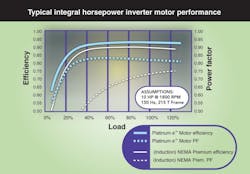
System efficiency is higher for a PMAC motor/drive setup from 40% to beyond 120% load. In addition, a PMAC motor exhibits higher power density than an equivalent induction motor: Rare-earth permanent magnets produce more flux for their physical size than the magnetic energy and resultant torque produced by an induction motor's squirrel cage rotor. In the latter, the effect of back EMF is also more pronounced: Back EMF reduces current and works to slow the motor — and gets larger as speed increases. When no load is present, it approaches the input voltage magnitude, reducing efficiency. Consider that, in general, certain PMAC motors are rated for variable or constant torque to 20:1 without feedback (open loop) or 2,000:1 for closed loop (with an encoder).
Speed (input frequency) has less effect on PMAC motor efficiency than it does on ac induction motors, which translates into energy savings at reduced speeds. PMAC motor losses (the inverse of efficiency) are 15% to 20% lower than NEMA Premium induction motors.
Depending on motor size, electric utility rate, and duty cycle, designers can realize full return on a certain PMAC motor purchases in one year. PMAC efficiency ratings are one to three indexes above NEMA Premium, which translates to 10% to 30% fewer losses than a conventional motor. Electricity is estimated to comprise approximately 95% to 97% of the total lifecycle cost of electric motors, so energy savings significantly reduce the total investment.
In short, due to their synchronous operation, PMAC motors also offer better dynamic performance and speed-control precision — a benefit in high-inertia positioning applications. Although the power factor with a drive may not be as high as a motor-only induction machine, PMAC motors generally provide higher power density due to higher magnetic flux. Therefore, more torque can be produced in a given physical size, or equal torque produced in a smaller package. Finally, PMAC motors generally operate more coolly than ac induction motors, resulting in longer bearing and insulation life.
If this was useful to you, download the complementary eBook from LEESON Electric. PDF download begins automatically.
About the Author
Voice Your Opinion!
To join the conversation, and become an exclusive member of Machine Design, create an account today!

Leaders relevant to this article: