How to Choose the Right Control Method for VFDs
Download this article in .PDF format
Motors account for at least half of the energy consumed in the U.S. Selecting the right control method for an application lets the motor run most efficiently while maximizing torque and overall performance. Efficiently run motors also use less energy and experience less downtime for greater overall savings.
For motors controlled by a variable frequency drive (VFD), the control method used in large part determines a motor’s efficiency and performance in an application. Once engineers and designers understand the advantages, disadvantages, and particular specifications for each control method, choosing the right one for any application becomes simple.
Control methods
Many people in the industry think control methods are the sequencing methods that control VFDs, as in 2- and 3-wire setups. Such 2- and 3-wire setups determine whether a VFD’s input-control terminals interface with maintained contacts or momentary push buttons to start and stop the drive. The control methods this article focuses on are perhaps more accurately called motor-control methods. They determine how VFDs control motors.
There are four primary types of motor control methods for induction motors connected to VFDs: V/f (volts-per-hertz), V/f with encoder, open-loop vector, and closed-loop vector. These methods all use pulse-width modulation (PWM), a technique that varies the width of a fixed signal by modulating pulse durations to create a variable analog signal.
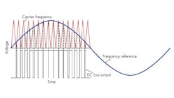
PWM is applied to VFDs by using the fixed DC voltage from the VFD’s DC bus capacitors. A set of insulated gate bipolar transistors (IGBTs) on the output side rapidly open and close to generate pulses. Varying the output pulses’ width in the output-voltage waveform can build a simulated AC sine wave. Even though the drive’s output-voltage waveform consists of square waves due to DC pulsing, the current waveform will be sinusoidal because the motor is inductive. All motor-control methods rely on a PWM voltage waveform to control the motor. The difference between control methods lies in how they calculate the motor’s voltage needs at any given moment.
V/f control
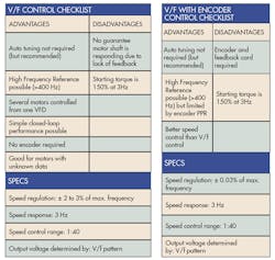
Volts-per-hertz, commonly called V/f, is the simplest motor control method. It is often used due to its “plug-n-play” simplicity and how little motor data the drive needs. It does not require an encoder and tuning the VFD to the motor is not required (but recommended). This means lower costs and less wiring. V/f control is often used when there is a demand for operation, which could exceed 1,000 Hz, so it is often employed in machine tool and spindle applications.
V/f is the only control method that lets several motors run from a single VFD. In such cases, all motors start and stop at the same time, and follow the same speed reference.
V/f has some limitations. For example, with V/f, there is no guarantee the motor-shaft is rotating. Additionally, the motor’s starting torque is limited to 150% of its output at 3 Hz. The limited starting torque is more than enough for most variable torque applications. In fact, just about every variable torque fan and pump app in the field uses V/f control.
The V/f method’s relative simplicity is partly due to its “looser” specifications. Speed regulation is typically 2% to 3 % of maximum frequency. Speed response is rated at 3 Hz. Speed response is defined as how well the VFD responds to a change in reference frequency. An increase in speed response results in quicker motor responses when the reference frequency changes.
Control methods also have speed-control ranges (expressed as ratios). V/f’s speed control range is 1:40. Multiplying this ratio by the maximum frequency determines the VFD’s minimum running speed at which it can control the motor. For example, with a 60-Hz maximum frequency and 1:40 speed control range, a drive using V/f control can control a motor down to 1.5 Hz.
A V/f pattern defines a ratio of voltage-to-frequency for the motor to follow and a VFD can have only one V/f pattern programmed at a time. The V/f patter, or curve, determines what voltage is output to the motor based on a given speed reference (frequency).
Operators or technicians can select preset V/f patterns in the VFD’s programming with a single parameter. Preset patterns are optimized for specific applications. Users can go one step farther, programming a custom V/f pattern or profile to tune the VFD to a specific application and motor being used.
Applications such as fans and pumps are variable torque loads. A variable-torque V/f pattern prevents faults and increases performance and efficiency. This pattern reduces the magnetized current at low frequencies by lowering the motor voltage at lower frequencies.
Similarly, constant-torque applications, such as conveyors, extruders, and hoists, should use constant-torque V/f patterns. Constant-torque applications need full magnetizing current at all speeds. So a straight slope is constructed and followed throughout the entire speed range.
In general, the VFD will output a voltage based on whatever speed the motor is set to while referencing the V/f pattern.
V/f with encoder
If an application needs more precise speed regulation, along with the ability to run at a higher reference frequency, an encoder can be added to V/f control. The encoder feedback tightens speed regulation down to 0.03% of the maximum frequency. Output voltage is still determined by the selected V/f pattern programmed into the VFD by a technician. This allows for high-speed control without high dynamic responses because voltage and frequency are predetermined.
This control method is not common because it entails the costs of an encoder and feedback card, and its advantages over standard V/f control are minimal. Starting torque, speed response, and speed control range are all identical to the V/f control. In addition, higher operating frequencies are limited by the how many pulse-per-revolutions the encoder generates.
Open-loop vector control
Open-loop vector (OLV) control is used for greater and more dynamic motor control. It independently controls motor speed and torque, much like DC motors are controlled.
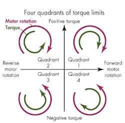
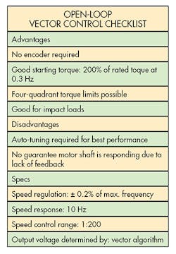
When running OLV, motors can produce 200% of their rated torque at 0.3 Hz. The higher starting torque at lower speeds opens the door for a variety of applications. This control method also allows for four-quadrant torque limits.
Torque limits primarily restrict motor torque to prevent damage to equipment, machinery, or products. They are broken into four different quadrants, depending on motor direction (forward or reverse), and whether the motor is motoring or regenerating. The limits can be set independently for each quadrant, or users can program an overall torque limit into the VFD.
A motoring condition is when the motor’s speed and torque are both in the same direction. For example, forward speed and forward torque would motor a conveyor in the forward direction. Regeneration is when the motor is being overhauled by the load. On an AC motor, when the rotor rotates faster than the magnetic field in the stator, it acts as a generator. This causes regenerated energy to flow back into the VFD.
A machine drill backing a screw out of a block of wood (reverse motor direction and negative torque) could use limits in Quadrant 3. And an unwinding application could use Quadrant 4 limits (forward motor rotation and negative torque). The motor would spin forward motor rotation to feed the line, but it would also need a negative torque limit due to regeneration caused by the line being pulled to create tension.
The current feedback loop in these VFDs lets users set torque limits and run in all four quadrants. As motor current increases, so does motor torque. Output voltage going to the motor can be increased if the application needs more torque or decreased when reaching a torque limit. This makes open-loop control dynamic, unlike V/f control.
In addition to torque limits, open-loop control has a quicker speed response of 10 Hz, letting it handle more dynamic responses to impact loads. For example, a rock crusher’s load constantly changes, depending on the size and quantity of rock being processed.
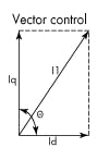
Instead of a fixed V/f pattern, OLV control uses a vector algorithm to find the best output voltage to run the motor. Vector control accomplishes this by using current feedback from the motor. Current feedback is measured via current transformers inside of the VFD. Constant current readings and rapid calculations performed in the VFD determine present torque demand and flux. Basic vector math breaks down the motor’s magnetizing current and torque-producing current into vectors. OLV control depends heavily on the motor dynamics, so some type of motor auto-tuning must be performed to ensure the VFD has as much motor data as possible.
With the help of reliable motor data/parameters, the VFD can calculate the magnetizing current (Id) and the torque-producing current (Iq) as vectors. For maximum efficiency and torque, the VFD must keep these two vectors separated by 90°. That 90°is significant because sin (90) = 1, and the value 1 represents maximum motor torque.
Overall OLV control results in tighter control. Speed regulation is +/- 0.2% of maximum frequency, and the speed-control range jumps to 1:200, allowing for low-speed operation without sacrificing torque.
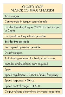
Closed-loop vector control uses a vector algorithm to determine output voltage, much like the open-loop control. The key difference is that closed-loop vector uses an encoder. Encoder feedback, paired with the vector control, means 200% of the motor’s rated torque is available at 0 rpm. This is a selling point for apps required to hold a load without moving, such as elevators, cranes, and hoists.
Encoder feedback allows for speed responses over 50 Hz and speed control ranges of 1:1500, the highest of all the control methods. Closed-loop control can also run a motor in torque-control mode. Torque control lets the VFD control motor torque rather than motor speed. This is needed in any application where torque is more important than speed. Winders, rewinders, capping, and web applications are good examples of where torque control is used.
