Selecting Pneumatic Components for Functional Safety
Download this article in PDF format.
To a machine designer, “stay safe” is not just a cheerful slogan or wishful thinking. Operator safety is a central design issue. The international standard, ISO 12100:2010 Safety of machinery – General principles for design – Risk assessment and risk reduction, gives designers a framework and guidance for designing machines that are safe for their intended use.
To start, a designer must assess the risks posed by the machine or parts of the machine. When risks are discovered, there is a three-step method of risk reduction. The first step is inherently safe design—design out the risk so that the machine can’t do anything to cause an injury.
However, in many applications, this is not always possible. Take, for example, equipment like presses, conveyors, or assembly lines where operators must interact with moving parts. Reducing risk of injury in these situations requires step two—building in complementary forms of protection. These could be physical barriers like guards or functional safety systems such as electrical or pneumatic safety circuits that detect a hazard and initiate a protective action.
The third step is to add passive safety measures, including warning signs or lights to reduce any residual risk left after taking the first two steps.
Designing Safe
The machine designer is ultimately responsible for analyzing the design for risks and incorporating functional safety where necessary. In most cases, functional safety consists of three parts: a sensor such as a light curtain or pressure switch to detect a hazard; a programmable logic safety controller (PLC) or safety relay; and an electrical, hydraulic, or pneumatic output to initiate the safety function.
Here are some safety functions engineers can incorporate to protect machine operators.
- Safe exhaust relieves the pressurized air in applications like winding machines, strapping machines, or tooling, where maintaining a pressure load in a pneumatic circuit during a hazardous situation could cause injury.
- Safe stop stops the movement of the machine upon detection of the hazard.
- Safe position maintains the load in precise position in addition to stopping an operation when a hazard is detected. This function prevents the load from moving until the situation is corrected.
- Safe reverse changes the direction of the load, for instance, by retracting the actuator so that the load actually moves away from the hazardous situation. This would be useful in applications such as welding machines.
- Safe limited speed allows users to move actuators at slower speeds for maintenance or test purposes, preventing risk of a hazard at full pressure and speed.
- Safe protection against unexpected startup protects workers against an unexpected movement of, say, an actuator.
When choosing which safety function is best suited to an operation or application, designers must be sure the function itself will not trigger another hazardous movement. For example, if exhausting a circuit would cause a part to drop, a safe stop or safe position function should be used instead.
Assessing and Reducing Risk
ISO 13849-1:2015 Safety of machinery – Safety-related parts of control systems states, “As part of the overall risk reduction strategy at a machine, a designer will often choose to achieve some measure of risk reduction through the application of safeguards employing one or more safety functions. Parts of machinery that are assigned to provide safety functions are called safety-related parts of control systems (SRP/CS)…”
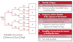
The first step in designing a safety function and selecting its components is to assess the risk, based on the severity of a potential injury, the frequency and length of exposure to the hazardous situation, and the possibility of avoiding the hazard or limiting the harm as well as the probability of its occurrence. The figure below shows how to use these factors to determine the performance level (PL) required of a safety function.
The required risk assessment and performance levels (PL) are determined by the machine’s safety function.
For example, if a minor injury could result from a hazard to which the operator is exposed infrequently or for a short time, and it could be avoided, the risk is low and the PL would be “a.” At the other extreme, if a serious injury or death could occur from a hazard that is continuous and unavoidable, the risk is high and the PL required would be “e.”
Once the designer determines what PL is required, that information can be used to select a design architecture and components for the safety control system, referred to in ISO 13849-1 as categories B, 1, 2, 3, and 4:
- Category B, suitable for the lowest-risk PL-a and -b, is a single-channel non-redundant safety system. A single fault leads to the loss of the safety function.
- Category 1 is also single-channel, but offers higher resistance to failure with proven-in-use components.
- Category 2 includes additional test channels and cyclical testing for safety functions, but a fault between test phases could lead to a loss of safety function.
- Category 3 is a dual-channel, redundant safety system. A single fault will not lead to the loss of the safety function, but accumulated undetected faults may cause that to occur.
- Category 4 is a dual-channel, redundant safety system where neither a single fault or an accumulation of faults can cause a loss of safety function. Clearly, if PL-e has been determined, a Category 4 system will be required.
Suppliers of pneumatic control valves for functional safety can direct designers to components and assemblies that meet application-specific PL and Category requirements.
Techniques to Avoid Hazards
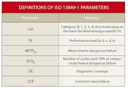
A valve manufacturer can supply the B10D value (i.e., how many cycles a random selection of valves can undergo before 10% of them experience dangerous failure) defined as a failure that has the potential to put the SRP/CS in a hazardous or fail-to-function state. The machine designer must calculate the mean time to failure for a dangerous condition (MTTFD) because they have access to data about operating times and cycles. Again, MTTFD refers to average operating life until up to 10% of units fail dangerously.
Redundant systems have two channels controlling the safety function. Therefore, if one fails, the other can still initiate the action. However, if a fault occurs in one during normal operations, only one is left to control the function in a hazardous situation, so the system is no longer redundant. To avoid this, redundant systems require diagnostic coverage (DC)—testing or monitoring that will signal the operation to stop until the fault is repaired. Many systems rely on a sensor sending a signal back to the PLC to stop the circuit and avoid restarting.
Valves with internal cross monitoring eliminate the extra step of electrical signaling. They are pneumatically self-monitored, and as 3/2 normally closed valves, will always exhaust when a fault is detected, depressurizing the system even if no power is available. They also will prevent restart as long as a fault is detected.
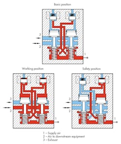
Illustrated are solenoid-activated safety valves with internal cross monitoring.
The solenoid valve highlighted in this article diagrams a two-channel safety valve with cross monitoring. In basic position, no compressed air (red color in the figure above) reaches the downstream equipment. In working position, the equipment is powered. The valve moves into safety position if one channel faults; for example, control is out of balance, a solenoid malfunctions, or the valve is contaminated. In this case, rather than keep the process running without redundancy, the valve automatically shuts it down without requiring a signal to the PLC.
Common cause failures (CCFs) are defined as the failure of multiple items resulting from a single event. For example, contaminants in the air supply could cause both valves in a redundant system to fail independently. ISO 13849-1 calls out six types of mitigation measures: separation/segregation, diversity, design/application/experience, assessment/analysis, competence/training, and environmental. Table F.1 of the standard defines each and assigns points for scoring measures taken to prevent CCFs. A minimum score of 65 points out of 100 possible is required to meet the standard.
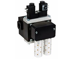
Machine designers must be sure they are using safety-related parts of control systems, such as this safety valve with cross monitoring, that meet risk assessment and reduction requirements. (Courtesy of Norgren Inc.)
Functional safety is ultimately the responsibility of the machine designer—no SRP/CS can compensate for a poor design. However, part of that responsibility is to select parts that meet the standards required by a good design. Designers should work with trusted suppliers with deep technical expertise and a robust product line to find just the right components to keep machines and their operators safe.
About the Author
Bernward Sprünken
Product Manager
Bernward Sprünken is Product Manager for IMI Norgren GmbH in Alpen, Germany, an IMI Precision Engineering branded company.
Bradlee Dittmer
Product Marketing Manager
Bradlee Dittmer is Product Marketing Manager for Norgren, Inc. in Littleton, Colo., an IMI Precision Engineering branded company.
