This file type includes high-resolution graphics and schematics when applicable.
Most engineers tend to rely on traditional fastening methods to join parts (see "Impact Riveting: The Old School Approach," below). However, a couple of similar, lesser-known techniques for putting heads on rivets and studs for permanent joints —orbital and radial riveting—can bring better results at lower costs for many applications.
Orbital Riveting
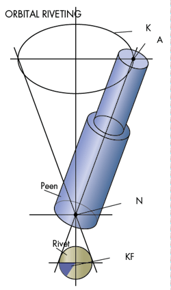
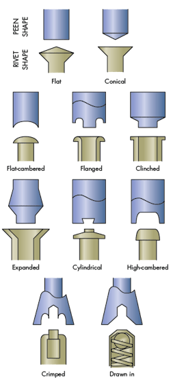
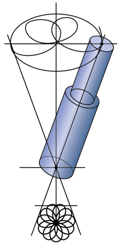
Orbital forming is a cold-forming process used on parts in which an angled peen or forming tool attached to a spindle spins 3 to 6 degrees off center and applies axial and radial forces to a portion of a part. This progressively moves some of that material, forming it into a predetermined shape.
The process works on a wide variety of malleable materials, including steel (even high-alloy steel with a hardness of 54), aluminum, brass, bronze, copper, lead, and zinc, as well as many polymer composites and other plastics, including ABS. Depending on the tool, the process can create swages, crowns, and flares, or, as it is most commonly used, put heads on studs and rivets (also called upsetting or bucking rivets).
Peens are shaped with the final shape of the finished part in mind. Specific peens have been designed to produce conical, flat, eyelet, and crown heads. The forming tools are usually made of M2 drill-rod steel and heat treated to a Rockwell C hardness of 60 to 64. On the riveting or forming machine, they are held in place by a setscrew and can be quickly changed.
In orbital riveting, also called radial or spin riveting, the forming tool is in contact with a small area on the part being formed at any one time. As a result, the compressive forces on it are 80% less than in impact riveting, a brute-force approach to riveting. The line of contact between the tool and rivet does not vary.
On each revolution of the spindle, the same line of contact is maintained. Because the same point on the tool is always in contact with the same point on the rivet, there is little friction and no tearing of the material. This means it will not create a galled or hammered finish. Solid rivets formed with orbital riveting will have smooth finishes whether they are crowned, conical, or flat head.
The lower forces reduce internal stresses in the final rivet and the parts being joined, which increases the finished assembly’s fatigue life. The lower forces also give the rivet’s formed head a smoother finish, eliminating cracks caused by impact riveting, and extend the life of the forming tool. But the constant side thrust on the rivet generated by the peen necessitates the use of a fixture to hold the workpiece steady and prevent lateral creep.
It takes three or four passes over the part to create a 0.02- to 1.5-in.-diameter hardened and slightly compressed head. This takes from 1.3 to 3 seconds. But it usually takes longer than that to manually or automatically load and position the parts being joined and insert the rivet. The forming time ultimately depends on the hardness of the rivet and its total surface area. Therefore, small-diameter rivets made of soft materials can be bucked quicker than thicker ones.
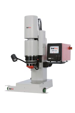
Equipment used for orbital riveting lets technicians monitor and control the forming process based on data that includes forming forces, variable rate of forming forces, form height, and clamp loads between fastened parts. This gives the finished rivets and joints consistency and uniformity. Other advantages of orbital riveting over impact riveting include:
• The forming forces do not usually exceed the strength of the rivet’s shank, so the process does not need to bend or swell the rivet’s shank.
• A smaller press can be used, which translates into a smaller footprint and a smaller motor, both characteristics that can save money.
• Because the forming forces are lower, the fixturing need not be as rigid and is less costly.
• Orbital riveting is practically silent and vibration-free.
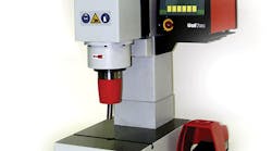
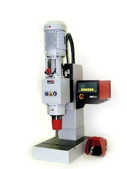
Orbital-riveting machines need less force than impact riveters. Pneumatic versions, for example, exert 1,000 to 7,500 lb. of force, while more powerful hydraulic orbital riveters can exert 6,000 to 50,000 lb. of force. Precision orbital machines spin the spindle at about 1,700 rpm. Heavier-duty machines run at 900 to 1,200 rpm.
Orbital riveting will not work on blind rivets because with them, the installation process requires access to both sides of the assembly.
Radial Riveting
Rivets can also be created using radial forming, which is similar to orbital forming. With radial riveting, though, a punch rather than a peen rotates around the workpiece, tracing out an 11-sided rosette path (actually a hypocycloid, much like what could be created with the Spirograph toy). It gently deforms the material. There is little axial force and the material predominantly flows radially.
Such little lateral force means fixtures and clamps are usually unnecessary. There is also little downward force, so rivets can be placed in brittle materials, including ceramics and bakelite. The lower forces extend the life of the tool. Thus, for metal rivets, this lets the material retain its grain structure and structural strength.
The punch itself does not rotate. This minimizes friction between the tool and workpiece and creates a smooth finish with no galling or scuffing.
One of the differences between radial and orbital riveting is that radial forming moves material at a constant speed and at a uniform rate. Orbital forming moves materials at different rates, with material near the rivet’s perimeter moving faster and farther than material near the center. This gives radial rivets higher joint strength.
Radial riveting also improves the electrical conductivity of metal rivets, according to some. As a result, it is well-suited for making rivets that serve as electrical contacts. The process also works well on delicate parts with small diameters (less than 1/8 of an inch). In fact, the process was originally developed to install tiny rivets in watches. Thanks to these two characteristics, it can be used to form rivets on printed circuit boards (PCBs) that connect components while also serving as an electrical pathway work on PCBs.
However, radial riveting is more complex and the forming tools cost more than orbital-riveting peens. It also takes longer to radially form a rivet than using the orbital process.
Impact Riveting: The Old School Approach
When most engineers think of riveting, they think of impact riveting. In this relatively simple process, a rivet gets placed automatically or manually in the jaws of the riveting machine. A force, usually a flywheel (hydraulic and hydra-pneumatic forces are also used), slams a driver into the rivet and through a hole drilled through the two or more parts being permanently joined. These parts are often sheet metal or flat panels.
For solid rivets, this force causes the shank of the rivet to swell to fill the hole. Then metal protruding from the two parts being joined gets compressed and cold formed in the rollset. The rollset is a tool that shapes the metal into a second head that holds the parts together.
For semi-tubular rivets, the rollset flares out the hollow end of the rivet, rolling it down to form the other head. It takes about 40% less force to install a semi-tubular rivet than a solid rivet.
Semi-tubular and solid rivets are usually made of steel, but they can also be made out of aluminum, brass, and stainless steel. Semi-tubular versions have shank diameters that range from 0.06 to 0.3 in. in diameter. Solid rivets can have diameters up to one inch wide.
In general, impact riveting is reliable, inexpensive, and quick, installing a rivet in as little as 0.5 sec. Up to four rivets can also be installed at once. This usually requires fixturing to hold the parts still and with the holes all aligned. With an offset driver, rivets can be installed more closely together so there is only 1/16th of an inch between heads.
To keep operators safe, many riveting machines have safety devices such as Lexan guards, light curtains, and dual-palm buttons. These buttons require that both the operator’s palms be on them before a rivet will be installed. This prevents any fingers from getting damaged in the installation process.
Looking for parts? Go to SourceESB.
