Hydrostatic linear guiding for standard design spaces
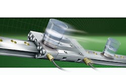
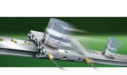
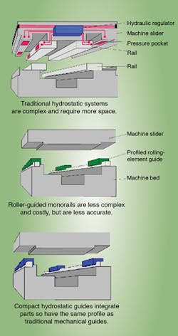
Now, newer compact hydrostatic linear guides address old issues. Built to the dimensions of standard profiled-rail linear guides, they fit within the same design space as typical recirculating bearing and guideway assemblies — to give engineers and machine builders the benefit of unmatched damping without requiring installation compromises.
Basic operation
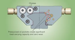
Hydrostatic guides consist of carriages with pressure pockets that ride on precision-honed guideways energized by a steady layer of pressurized oil. Each carriage is comprised of a steel saddle plate featuring two endpieces. At one endpiece, an integrated pressure regulator supplies oil to the carriage's pressure pockets; at the other suction-side endpiece, depressurized oil is extracted via an oil circuit. It's upon the oil-filled pressure pockets that a hydrostatic guide is loaded.
More specifically, hydraulic oil is fed to the pressure side and chambers under constant pressure: Integrated chokes are set so that the carriage is optimally positioned on the guideway and lifted off evenly to a gap height of 0.015 mm.
This integral hydraulic control system is what allows the unit to fit into the same standard design envelope as a conventional roller profile rail system.
How much oil and pressure is required? A hydrostatic guide with a 45-mm wide rail has a flow rate of approximately 1.2 liters per minute at an operating pressure of 100 bar with an oil viscosity class of ISO VG 46.
To prevent damage in the event of a crash due to a partial or complete loss of pressure, the working pressure pockets are lined with a sliding material to create a failsafe for the system. Note that to protect this lining during installation, the carriage must be oiled before being pushed on to the guideway.
Rigidity, accuracy, and performance
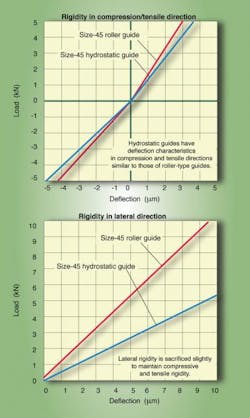
One might assume that moving loads on a film of oil would not provide the rigidity necessary for maximum machine performance. To the contrary, when standard design specifications are met, the tensile rigidity of a hydrostatic linear guide is roughly equal to that of a similarly sized roller bearing and guideway assembly. Note that this is based on a two-rail, four-carriage system with two carriages per rail. With this arrangement, rigidity in the compressive direction is 1,300 N/µm; in tensile and lateral directions, it is 1,200 N/µm and 950 N/µm respectively.
This includes deformation of the hydrostatic guide and screw connections to the adjacent construction. The rigidity of the carriage prevents any deformation of the pressure pockets, which is critical in maintaining equal pressure distribution within the carriage.Rigidity can also be enhanced by increasing the oil pressure via a valve setting. In mechanical systems, higher preloads on the rolling elements are required to boost rigidity. Unfortunately, what also results is increased rolling friction and an exponential decrease in bearing life.
Hydrostatic carriages, on the other hand, run on pressurized oil, so there is no increase in friction and no effect on the system's operating life. Friction is independent of load until the load limit is reached.
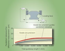
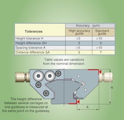
Running accuracy partially depends on the straightness, accuracy, and rigidity of the structure to which the hydrostatic guide is mounted. System straightness is only achieved when the guideway is pressed against a controlled datum surface. Manufacturers supply mating-surface tolerance guidelines, as well as permissible height differences; deviations impair overall accuracy, affect the preload, and may even result in an inoperable system.
In general, surfaces should be ground or precision milled to a mean roughness value of Ra1.6. If an application requires particularly high running accuracy, or if soft substructures and movable guideways are used, the manufacturer's input is recommended.
Running characteristics of hydrostatic systems are useful as well. Accelerations of up to 100 m/sec2 (approximately 10 gs) and speeds of 120 m/min. are typical.
Damping
Vibration in machine tools — induced as a result of blade contact shocks, tool wear, and other disruptive forces from outside influences — can be a serious problem. The numerous resulting resonant frequencies can significantly degrade workpiece accuracy and surface quality. The lubricant film separating the components in hydrostatic guidance systems provides vibration damping that counteracts these effects.
The carriages in traditional monorail guides cannot accommodate vibration damping; for isolation from adjacent structures, they require additional features such as passive damping elements.
In passive elements, oil is fed under no pressure and only damps when subjected to an impulse. These elements are usually positioned between the load-bearing carriages. However, to optimize performance, especially when bending vibrations occur, the damping elements must be positioned at the largest point of deflection. This requires extensive knowledge of a machine's vibration patterns.
Traditionally, machine builders addressed damping by integrating hydrostatic elements within machine slides. These slides ran on high-accuracy precision-ground ways. This design was very expensive and required a larger design envelope. Another drawback was the high oil loss during operation, which required troughs to recapture the contaminated oil, and the maintenance of a high-end filtration process.
The advantage of newer hydrostatic guide systems is that they combine the high-quality damping of traditional designs with the performance and flexibility of rolling profile rails. Damping values for these units can exceed 470,000 kg per second.
Specific considerations
Hydrostatic guide systems can be supplied in a maximum length of 3,000 mm standard and up to 5,900 mm by special request. Due to the pressurized nature of the carriages, joining guideway sections is not possible. In addition, carriages are matched to the rail and cannot be interchanged. The choke gaps are set based on the specific carriage and rail combination.
The oil feed pipe to the pressurized side of the carriage must have a larger diameter and be reduced down at the carriage input — so as to guarantee flow at the input side. Alternatively, in the return pipes, the resistance through the extraction pump must be uniform and as low as possible.Once oil has left the carriage, the diameter of the pipe should expand to ensure that dynamic pressure in the extraction pipe does not exceed 0.2 bar. The hydraulic unit must also be fitted with a pressure switch linked to the machine's control system so that movement of the hydrostatic axis is permitted only when there is sufficient pressure.
Elastic double lip seals on the end faces and sealing strips on the carriage undersides protect against contamination and maintain the hydraulic oil in the carriage.
Interchangeability
Hybrid machine approaches are influencing decisions on the use of hydrostatic guide assemblies, as they allow manufacturers to more precisely define components (such as bearings) based on specific customer requirements. This maximizes flexibility in the selection of technologies appropriate to the specific application — including hydrostatic bearings where suitable.
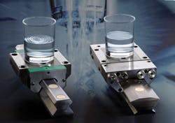
The ultimate advantage is that these guides are interchangeable and comply with the same ISO/DIN mounting specifications for monorail guidance systems. This allows machine manufacturers to offer both options for the same machine platform.
For more information on Schaeffler Group HLE series hydrostatic compact linear guidance systems, call (803) 548-8500 or visit schaeffler.us.
Machining results: Hydrostatic versus conventional roller guides
In high-speed machining and, in particular, in high-precision grinding applications, hydrostatic bearings increase cutting capacities and speeds, and improve surface quality and machining accuracy. They also damp loads at the point where the load is applied to protect against vibration generated in machine tools by blade contact shocks, tool wear, regenerative effects, and other disruptive but common forces.
Because the latest hydrostatic guides fit DIN design envelopes and mounting dimensions for monorail guidance systems, they have identical geometrical mounting dimensions and profile outlines. This is a feature that allows engineers to supply several performance classes with one machine to cover various machining requirements. For example, standard guides can allow for perfect surface quality and accuracy in standard machining, or hydrostatic guides can be substituted to get an increased cutting rate, cutting depth, and tool life (while maintaining quality and accuracy) from the same machine.
The operating load in machine tools is similar to the standard monorail guidance system. This guidance system can support loads from all directions and moments about all axes — regardless of the direction of motion.
