New Screws Cut Weight When Joining Parts and Sheets of Metals
It is said that for every 100 lb of weight removed from a vehicle, its mpg improves by an average of 1% to 2%. This is critical to the auto companies that must find ways to increase their average corporate average fuel economy (CAFE) rating to 53.4 mpg by 2025. That may not seem too onerous until one realizes that the starting point for those OEMs is model year 2011, when regulations set the standard at 27mpg. The smart OEMs, therefore, are already getting to work and combining many new technologies and processes on their journey toward a CAFE of 53.4 mpg.
A recent example of Ford’s work is the relatively new aluminum-body Ford F150. In many ways it marks an outstanding achievement in automotive lightweighting, reducing the previous model’s weight by nearly 700 lb. As remarkable as this weight reduction is, it would not be possible without state-of-the-art advances in “enabling” fastening technology.
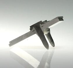
Until now, much of the focus on new fastening technologies has been on adhesives and self-piercing rivets. However, in the mix of enabling technologies, a totally new type of thread-forming fastener deserves recognition for providing functionality not possible with other fasteners. This state-of-the-art technology was developed and first brought to market by EJOT Industrial Fasteners of Germany, a global firm that develops thread-forming and specialty fasteners. The fastener, known as the EJOT FDS (Flow Drill Screw-driving) screw is a self-piercing, self-extruding, and self-thread-forming screw. This means it combines several functions in one screw.
* The FDS screw overcomes many of the challenges posed by today’s lightweight automotive body structures, including:
* Difficulty in fastening composite joint stack-ups, such as aluminum to steel, magnesium to steel, and even one aluminum grade to another.
* Fastening a joint when access to only one side is available, such as when an aluminum sheet is attached to an extruded or hydroformed tube, or space and part geometry restricts or prevents tool access for bottom-side installation.
* Creating a strong joint that provides the necessary clamping load without stripping or failing.
* Easy to repair or replace, if necessary.
* Low total cost per joint.
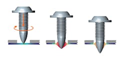
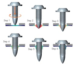
The FDS screw employs “flow drill screw driving” technology to pierce the upper and lower layers of aluminum and create an extruded boss in the lower layer. The screw then forms a metric screw thread in the newly extruded boss and is tightened to develop the desired clamping load that pulls and holds the joint tightly together.
During installation (see figure above), the first stage involves rotating the screw at up to 5,000 rpm (Step 1). The combination of high rotational speed and geometry of the special point locally heats the material into a plastic state, facilitating both the piercing of the upper sheet (Step 2) and forming the extrusion in the lower sheet (Step 3). Once the point is through, the screw uses its thread-forming region to create threads in the sheet and extruded boss (Step 4). After threads are formed, the material stack behaves like any other tapped-nut member. The screw is finally torqued to a predetermined level which safely develops clamp load without stripping the joint (Step 5 and Step 6).
Although the Ford F150 represents the classic application for this type of fastener—joining thinner aluminum onto thicker aluminum— the fastener is also versatile, provided that the application rule of thumb “thin on thick” or “soft on hard” is followed. In a practical sense, this means that when fastening aluminum to aluminum, the thinner section should be on top and thicker one on the bottom. It also means, however, you can fasten thicker aluminum stock to thinner and stronger mild steel.
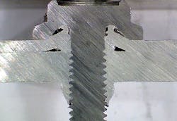
The figure above shows a joint with two aluminum layers where the thinner layer is on top and thicker on the bottom.
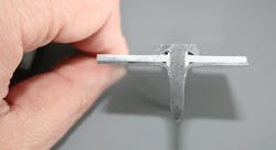
The figure above shows the case of a “soft on hard” style of joint, with a softer and thicker aluminum upper layer and thinner but stronger steel bottom layer.
One of the appealing advantages of FDS screws is their ability to pierce the top sheet, thus eliminating the need for a clearance hole. This helps designers when there are many consecutive joints in series and tolerance compensation would be tricky. Naturally, because clearance holes aren’t necessary does not mean the joint cannot be designed with one if it would be an advantage. In fact, joints with top clearance holes let FDS screws be used with thicker or high-strength steels and carbon fiber structures in the top layer that would otherwise not be feasible.
FDS screws also overcome the challenges presented by multiple-layer stacks. Using a single fastener to join more than two layers can be a valuable asset to designers. In many cases, all the layers can be pierced without any clearance holes, although it is common and usually desirable for designers to engineer clearance holes in either the top or center sheet to simplify the joining process. The alternative is to use support from underneath to clamp the joint and prevent sheet separation. The figure below shows an example of a three-layer aluminum joint.
Perhaps the most significant advantage and most highly used feature of FDS screws is their ability to self-pierce with no underside support. This is extremely valuable as it opens up opportunities for the screws to be used on extrusions or tubes that do not allow reverse side access. This is also true for tight spaces or where the geometry of the fastened layers would make reverse-side access extremely challenging.
However, there are several limitations that should be considered. The highest strength of material that can be joined with this method is approximately 600 to 700 MPa. The maximum steel thickness is approximately 1.5 mm for 700MPa ultimate strength (more, if the UTS is below 700 MPa) and for aluminum it is 4 mm. Additionally, when piercing without a clearance hole, a small amount of material flows up rather than down in the extrusion direction. This means the screw head must be undercut to seat flush.
It is also possible to create gaps between layers. However, as long as the gaps are contained within the cylinder represented by the outside head perimeter, they are considered acceptable. The image below shows an example of an undercut head and a joint with no clearance holes.
FDS screws hold great promise for automobile OEMs and suppliers as they pursue lightweight structures. It is no longer just a good concept but rather a proven technology with hundreds of individual joints applications in the Ford F-150, Audi TT, and Audi Q7. As more models use aluminum sheets and structures and require only one-sided-access connections, FDS screws will continue to gain popularity and find application next to their adhesive, SPR, and clinching-technology cousins.
Looking for parts? Go to SourceESB.
About the Author
Laurence Claus
Laurence is President of NNi Training and Consulting Inc. He holds a BSME from the University of Illinois, is a Certified Six Sigma Black Belt, and has almost 30 years of experience in the fastener industry. Prior to forming NNi Training and Consulting Inc., he was Vice President of Engineering with a prominent automotive fastener manufacturer. He regularly contributes to industry fastener standards activity by currently serving on multiple fastener standards committees, ASME B18, ASTM F16, ISO TC 2, and the SAE Fastener Committee and until recently on the National Aerospace Standards Committee (NASC) as a Technical Advisor. He is very engaged with the Industrial Fasteners Institute and coordinates their in-house training activities.
