|
Authored by: Stephen J. Mraz Senior Editor, [email protected] |
Control surfaces on aircraft — the moving elevators, flaps, and ailerons on the trailing edges of the wings and tail — have long been used by pilots to control a plane’s pitch, roll, low-speed lift, and climb or descent rates. But could they be replaced with moving blades of air? That’s the question researchers at several U. K. universities tried to answer when they designed and built the Demon UAV. If so, it would let aerospace engineers eliminate a host of moving parts subject to wear, icing, and failure. It could also lead to stealthier planes and drones because fluidic controls don’t leave gaps in the surface of the aircraft, nor do they move to present a larger or changing cross section to radars like movable ailerons and elevators do.
The Effect
The major goal of the research project was to see if fluidic controls, those based on the Coanda Effect, could exert control forces on an aircraft. The Coanda Effect, discovered in the 1930s, states that a fluid or gas will hug a convex surface if directed tangent to it surface, and this flow can entrain surrounding gas or fluid to follow that surface as well.
This means that air blown along a wing will follow the wing’s contours. So air blown along the top surface of a wing ends up increasing lift, which is perpendicular to the surface of the wing. And air blown along the bottom of the wing also increases lift, but in the downward direction.
On the Demon, researchers used what they dubbed fluidic controls — devices that could blow air either along the top or bottom surface of the wing’s trailing edge — to replace ailerons and elevators on a delta-winged drone. This lets them manipulate lift and drag over the wing and both steer and control the aircraft. They used a pair of similar devices to exert the same Coanda Effect on a four-sided engine nozzle. It gives ±90° of vectored pitch control with a nozzle that doesn’t move.
The plane
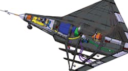
The U. K. team based their new drone on a previously successful UAV, the Eclipse, but had to increase size by 15% and add several new features. For example, to ensure there was enough pressurised air to send through the fluidic controls — especially to the thrust-vectoring nozzle during landings, when engine settings are low — the team added an auxiliary power unit mounted in the nose. It consists of a small turbine, fueled by the same aviation gas the main jet engine burns, which turns an air compressor.
As the weight of the aircraft climbed by at least 12 lb, the team also exchanged the Olympus jet engine and its 51 lb of thrust for a Titan engine and 88 lb of thrust.
To keep expenses down, landing gear was fashioned out of model aircraft wheels and tires, along with brakes, shock absorbers, and cables from mountain bikes.
The Demon’s airframe was constructed of carbon-fiber composites, which keeps the aircraft light and responsive to small control forces. For more structural support and to provide a skin, the team applied biaxial woven fabric, which easily drapes to make complex curved surfaces without wrinkles. Unidirectional tape was added in areas that needed additional stiffness. All fabrics and tapes were 0.25-mm thick, giving a good compromise between layup times and being able to adjust thicknesses. The final structure relies solely on adhesives — there are no mechanical fasteners. The floor for the payload bay was built from an aluminum alloy. It provides a place for the nose landing gear, APU, and batteries to be mounted.
The trailing edge of the Demon’s wings were modified to carry both conventional and fluidic ailerons and elevators. Each surface uses fluid controls with two submillimeter slots parallel to the trailing edge — one above the trailing edge and one below. Radio-controlled hardware lets researchers switch between the two during flight tests.
The APU provides air for the wing’s fluidic controls at 0.5-bar gauge and 80°C. The thrust-vectoring controls use air pressurized to 4-bar gauge and 250°C bled from the main engine. But this air first passes through a bypass shroud, cooling the 800°C engine air down to 250°C to protect the aircraft’s surface. Higher pressure air is used for thrust vectoring because the researchers discovered that blades of air or fluidic controls should have twice the velocity of the primary airflow being manipulated.
How well the fluidic controls work is still being evaluated and further tests are planned.
