It takes considerable time and effort to manufacture “perfect” surfaces. The mirrors on NASA’s James Webb Space Telescope, with a surface area of about 25 m2 and finished to accuracies of 25 nm, took nearly eight years to fabricate and polish. Or in a more down-to-earth example, 24 specialists polished the sculpture “Cloud Gate” by artist Anish Kapoor in Chicago’s Millennium Park for several months as the final manufacturing step. The gigantic stainless-steel “bean,” weighing over 99 metric tons and measuring 10 × 20 × 13 m, features a near-perfect, seamless surface that mirrors the Chicago skyline.
Related Articles
- Absolute encoders let water cannon douse flames accurately
- Total shutdowns not needed with safety controls based on encoders
- Low-cost servomotors include encoder, drive, and controller
Flawless surfaces are similarly a frequent goal in the machine-tool industry, particularly in moldmaking. Here, however, economics play an important role. In today’s markets, parts with tight tolerances and high surface quality must be produced quickly, and that presents a special challenge. Manufacturing high-quality molds, for example, requires rapidly removing large volumes of material during roughing and then precisely and painstakingly finishing the mold to a near-perfect surface. Otherwise, the moldmaker faces additional manufacturing steps — manual polishing, for instance — that add production time and costs.
In such operations, the cutting machine’s structure and mechanics, and the corresponding performance of the controls, no doubt play important roles. But equally important for optimal milling and finishing is the machine’s ability to accurately measure motion parameters. To produce parts with high-quality surfaces, it’s critically important that encoders generate signals with extraordinarily small deviations — within one signal period (interpolation error). Otherwise, excessive interpolation errors lead to problems like periodically recurring irregularities on the workpiece surface, which are particularly objectionable in moldmaking.
This file type includes high resolution graphics and schematics when applicable.
Surface defects stand out
The human eye is sensitive to even the smallest structural changes or defects on a surface. A pixel error on a computer monitor, for example, even with a display of up to 5 million pixels, is immediately visible. The human eye is even more sensitive to periodic surface faults. Test workpieces show that periodic form errors as small as 0.2 µm are clearly visible. Particularly in moldmaking, these form deviations, although they don’t affect accuracy, are undesirable and require expensive rework.
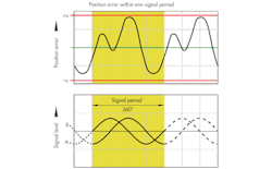
Surface errors on part surfaces appear as shadows or fluctuations in contrast, and customers perceive them as defects. They are due to fundamentally different causes: machine vibrations that disturb the machining process, or short-period errors in the axis encoder. This discussion centers on the latter: surface errors caused by position errors within one signal period — that is, interpolation errors.
Encoder position errors
An encoder’s direct resolution is usually insufficient for modern machine tools. Therefore, the encoder’s electronics uses interpolation processes to subdivide the two periodic analog (typically sinusoidal) scanning signals, termed A and B. Interpolation that subdivides the signals by factors of 4,096 (12 bits) and greater are typical. This makes it possible to start from measurements with relatively large graduation periods and attain the measuring steps needed for controlling machine tools. For example, Heidenhain LC 100 and LC 400 encoders offer measuring steps of 0.001 µm.
Interpolation processes operate faultlessly as long as the two sinusoidal output signals are ideal. That is, they have exactly the same shape, amplitude, and on-off ratio, and they are phase-shifted to each other by exactly 90°. In the real world, deviations generate errors that repeat themselves with each period of the scanning signals. Controls engineers therefore speak of errors within one signal period, or interpolation error. Several factors determine the size of position errors within one signal period:
• Size of the signal period
• Homogeneity and period definition of the graduation
• Quality of scanning filters
• Sensor characteristics
• The stability and dynamics during subsequent processing of the analog signals.
Effects Of position errors
Today’s moldmaking industry demands workpieces with increasingly complex geometries. As a result, five-axis machining using combinations of all axis movements is now commonplace. Often, however, if an inclined or curved machining surface is manufactured by simultaneously interpolating encoder signals for more than one NC axis, the interpolation error translates directly to the workpiece.
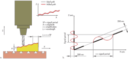
This becomes especially apparent when machining an inclined surface with a small slope angle. The interpolation error of the Z-axis encoder projects onto the inclined surface and becomes visible, often as a wave pattern on the workpiece. Because of the inclination, an n-fold enlargement of the signal period appears in the tool path. That is, while the Z axis moves by only one signal period, the X axis moves n times more. A wave appears on the inclined workpiece surface with a wavelength that corresponds to the n-fold signal period of the Z-axis encoder.
Because all sorts of inclined surfaces are manufactured when machining free-form surfaces, there will always be the corresponding amplification of the signal period.
Workpiece surfaces have a flawless appearance when interpolation error amplitude is less than 100 nm. Starting with an interpolation error amplitude of approximately 200 nm, the effects on milling become visible. Greater interpolation errors result in optically disturbing form deviations. A wavelength of 0.5 to 5 mm is especially easy for human eyes to detect.
Machining example
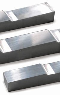
Consider three workpieces manufactured by multipass milling with a 12-mm ball-nose cutter. Each process used a different encoder with a different interpolation error. The results on surface finish are readily apparent, as shown in the accompanying images.
An encoder with an extremely small interpolation error (<100 nm) was used for the first workpiece, in this case a Heidenhain LC 100 Series linear encoder. The workpiece surface appears perfect.
Encoders with larger interpolation error present a different picture. Because the feed axes follow a higher interpolation error, a conspicuous wave pattern appears on the workpiece surface.
The second image shows the result of milling when the encoder has an interpolation error of 200 nm. A wave shape is clearly visible. The last image shows a part manufactured using an encoder with a 500-nm interpolation error. The workpiece surface has a prominent wave shape.
Precision encoders
Encoders with very small interpolation errors are necessary to mill workpiece surfaces without visible wave patterns. Heidenhain LC 100, LC 400, and LF linear encoders, for instance, offer the requisite accuracy as well as the durability needed in machining environments. The basis of their high signal quality is an extremely precise Diadur measuring grid and highly accurate single-field scanning.
The Diadur process generates precision graduations composed of an extremely thin layer of chromium on a glass or glass-ceramic substrate. They form a grating with line widths of 0.25 to 10 µm, depending on the model, and are a key factor in the accuracy of these encoders. The graduations consist of lines and gaps at defined intervals with little deviation, forming structures with high edge definition. These graduations resist mechanical and chemical influences as well as vibration and shock, and they have a defined thermal behavior.
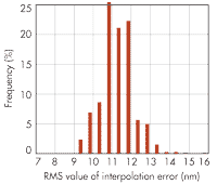
This is the basis for encoders with extremely high precision and a small position error within one signal period. For example, the maximum interpolation error of the LC family linear encoders is significantly less than 100 nm.
Resources:
Heidenhain Corp., www.heidenhain.com


